Q: What stops F1 racing cars from a speed of 200mph (320km/hour) in 4 seconds and slows airliners so they don’t run off the end of the runway when they land?
A: Carbon disc brakes and pads.
Carbon has replaced steel in these extremely arduous braking applications because:
- It is far lighter than steel
- It maintains its strength at high temperature
- It dissipates heat efficiently
- It has high friction at working temperature
- It is not susceptible to distortion and has excellent wear resistance which gives it a long working life.
- The coefficient of friction increases with temperature, making braking more effective.
- Discs and pads are ventilated to dissipate the heat generated during braking.

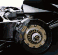
Carbon disc brake on F1 Grand Prix racing car
Carbon brake discs typically take about 6 months to make. The discs are made from layers of high purity carbon fibre matting ‘stitched’ together into a wad to form a blank roughly the size and shape of the finished item. The carbon fibre wad is then put in an oven at around 1,000°C where it is exposed to an atmosphere rich in hydrocarbon gas for hundreds, or even thousands, of hours. This causes the layers of felt-like material to fuse together and form an extremely strong, solid carbon blank virtually free from voids and inclusions. The resultant blank is then machined to finished size.
The Issue
Coventry-based Dunlop Aerospace Braking Systems (DABS) is a leading manufacturer of carbon disc brakes for military and civilian aircraft. When they decided to improve product quality by bringing greater control to the stitching operation, so they could take on a special project to manufacture heat-resistant carbon tiles for lining the JET (Joint European Torus) experimental nuclear fusion
reactor, DABS approached my company to design and build a programmable X-Y table for automating the press on which the process is carried out.
DABS gave me full responsibility for:
- Designing and building a reliable X-Y table to fit into a tightly constrained space
- Installing the X-Y table on the existing press and commissioning the machine
- Developing a PC-based software package for generating product recipes that are downloaded to the Trio MC206 controller via their LAN (local area network)
The stitching operation is done on a needling machine which has a bed of small, sharp, serrated needles that are pushed through each layer of carbon fibre matting in turn. The needles drag fibres down through the matting that binds it together and results in its felt-like quality, and also binds it to the layer below. In this way, the carbon fibre blank is given some strength for handling and the tiny holes help the hydrocarbon-rich gas permeate through the wad of material.
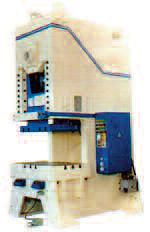
The needling machine is actually a crank press that operates at about 100 strokes per minute. The carbon fibre matting is bonded to a rubber backing attached to a steel plate that sits on the bed of the press and is held down by electromagnets. The bed of needles is attached to the moving slide. The needles are arranged on a 10mm square matrix over an area about 700mm square, to accommodate the largest component when the force required to push the needles through the matting is about 2,000kg and to retract them is about 500kg. The wad is built up in layers, with each layer being ‘stitched’ before the next layer is added, achieving a thickness of 1-11/4 inches/25-32mm. The bed is lowered by
the thickness of one layer prior to the next layer being added.
The need for an X-Y table for positioning the blank arose for two reasons: firstly, DABS wanted to needle each layer with a variable pitch between stitches as small as 1mm and, secondly, the position of the stitches in each layer has to line up exactly with the layers below. The X-Y table sits on the bed of the press and has to withstand the maximum insertion and retraction forces.
The Solution
Allowing for the electromagnets and the maximum thickness of the blank, plus the thickness of the stripper plate, the X-Y table had to be designed to be no more than 90mm in overall height to fit in the throat of the press. It also has to move between ‘stitches’ during the time the needles are inside the stripper plate, which is only a fraction of a second, which means that movement of the X-Y table has to be precisely synchronised with press operation. Travel in the ‘X’ direction only needs to be the pitch between needles (i.e. 10mm), so this axis is limited to 100mm travel, whereas in the ‘Y’ direction it has to move the table clear of the press for loading and unloading, so this axis has 850mm of travel.

Crank Press
The design was made even more challenging due to space restrictions within the frame of the press, which meant that the X-axis motor had to be ‘hidden’ inside the mechanism rather than be mounted external to it.
We designed and built a compact, robust X-Y table using Control Techniques brushless servo motors for driving the axes via ballscrews. It is topped by a solid steel plate which carries the electromagnets for holding the workpiece and which also helps to keep the abrasive carbon dust generated by the needling process out of the mechanism.
We also designed and built the electrical and control system, using a Trio Motion Technology MC206 motion coordinator for controlling operation of the complete machine including the X-Y table and press. They also created a CAD programme for running on a PC that allows DABS engineers to generate applications programmes (or product recipes) automatically for the MC206 by inputting stitching patterns as a series of parameters, as opposed to programming every individual stitch, and visualising the patterns on the PC screen. The applications programmes are then uploaded to the MC206 via the internal LAN (local area network).


Follow Tim!