I had invented a simplified motion controller in which each separate axis has its own dedicated processor, or motion control chip. An ideal opportunity arose for developing the controller against a real application when Blackburn-based carpet tufting machine manufacturer, Thom Engineering Limited, approached my company with a requirement for controlling 2,000 individual yarn feed motors simultaneously.

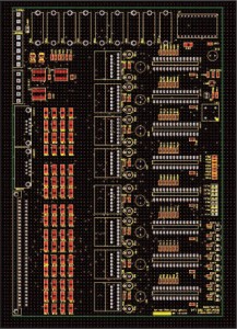
Layout of the PCB generated by the CAD system incorporating eight separate motion controllers
The first task was to make the prototype controller. At the core of the controller is a Digital Signal Processor (DSP) for handling the complex calculations associated with motion control applications. Having chosen the components, I laid out and joined them on the CAD system to make one complete axis control circuit, taking into account critical issues such as the position and rating of heatsinks to dissipate the heat generated by the motor drive circuit, and isolation of sensitive components from sources of electrical noise. The routing of the tracks connecting the devices was done automatically by the CAD software and a design file was generated from which the PCB (Printed Circuit Board) could be fabricated.
Having populated the PCB and tested it electrically, I developed the embedded code – in assembly language, the native code of the microprocessor – which would define the functionality of the controller. Once the application had been proven for controlling a single motor, I was ready to scale it up for multiple axes. The stepper motor chosen for paying out the yarn draws a nominal current of 1amp. Based on the thermal characteristics of the drive amplifier, I determined that the optimum density would be eight motor drive circuits on a 6U, rack-mounted Eurocard, which would share resources such as the clock and the 5Vdc supply for powering the DSPs. This also called for another, very practical layer of design, to house the PCBs, to provide connectors capable of handling the real-world current and voltage required for driving the motors, and to build in both immunity to the electro-magnetic noise in the environment and compliance with the relevant EU directive concerning noise.

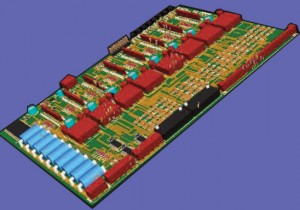
Computer-generated 3D view of the finished, populated PCB
By far the greater part of the work in developing the controller was the software. This is divided into two main sections: one deals with control of the yarn feed motor and synchronisation with the tufting mechanism, whilst the other handles the processing of network messages and the interpretation and execution of special commands created specifically for this application. At the heart of each individual axis controller is an infinitely variable electronic gearbox which allows the length of yarn paid out to be modified every machine cycle. Each controller can store up to 1000 move instructions in flash memory, defining patterns that can have up to 1000 different length tufts before it must be repeated, with each move being a different ratio between the yarn feed mechanism and the tufting mechanism. The tufting mechanism is driven by a common line-shaft fitted with an encoder that produces a stream of position pulses and one reference pulse per revolution. When the controllers see the reference pulse they execute their next move, or gear ratio, which is interpolated with the position pulses derived from the shaft rotation to feed the yarn smoothly. The development used much of the expertise I had built up over the years. For instance, the network – MCSNet – I developed for communicating between controllers and an external PC is modelled on the industry-standard MODBUS protocol which is well proven and freely available for anyone to use. However, this is limited to addressing 255 nodes, whereas MCSNet will address 65,536 nodes, although the highest address is used for public broadcasting across the network. MCSNet also includes special commands specific to the application but uses the same error checking routines as MODBUS to ensure that messages have been received correctly. In order to keep component count and hence board cost down to a minimum, I implemented many functions in software that would otherwise be done by dedicated chips. For instance, the drive features microstepping that allows each step of the motor to be electronically divided into smaller increments, so that standard motors designed for 200 steps/rev operate at 6,400 steps/rev, producing smoother motion that avoids yanking the yarn. It also delivers a constant current and hence constant torque across the motor’s speed range, improving performance, and it has a stand-by mode which reduces the current automatically when the motor is idle, to reduce heating, all of which are achieved entirely by the software running in the microprocessor.


Follow Tim!